
All projects
Machine Manufacturing
Vibrating Feeder Manufacturing
Workshop manufacturing of a welded body, material bed, spring groups, vibration drive and support chassis for controlled transfer to the next process equipment.
Project typeWorkshop-Manufactured Auxiliary EquipmentStatusManufacturing
Manufacturing summary
01 · Project need
What the project needed to achieve.
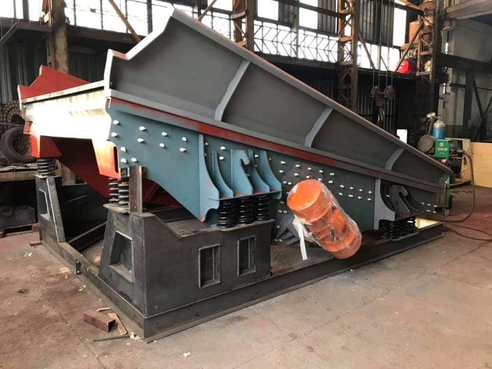
The published workshop photograph documents the manufactured condition of the feeder body, material bed, spring groups, vibration drive and support chassis. Customer-specific process duty and field-interface data are not published.
Real Manufacturing Image
Welded body, spring groups and twin vibration drive.
The workshop photograph clearly shows the material bed, support chassis, coil springs and vibration motors on both sides.
Completed vibrating feeder and support bodyEquipment and process duties
What each system does in the line.
Welded Body
The main machine body combining the material bed, side plates and reinforcements in one rigid structure.
Material Bed
The inclined conveying surface along which material advances under vibration.
Support Chassis
The welded base carrying the feeder body, spring groups and drive equipment on one reference structure.
Spring System
Elastic supports between the body and fixed chassis that permit vibration while limiting transmission into the support structure.
Vibration Drive
The twin vibration-motor arrangement visibly applying motion to the feeder body.
Connection Points
Mechanical interface regions connecting the machine to field feeding and discharge points.
02 · Estilo scope
What the project covered.
Manufacturing of the feeder body and support chassis
Mechanical layout of the vibration system
Preparation of connection and field interfaces
Published engineering context
What the published record supports.
Material Path
The inclined bed and side plates define the main geometry for controlled movement from feed inlet toward discharge.
Vibration Isolation
Coil springs between the body and support chassis provide the elastic connection required for vibration.
Drive Layout
Twin vibration motors are visibly mounted on accessible sides of the body; power and speed are not published because they are absent from the project record.
Chassis & Connections
The welded base carries machine components on one reference and provides the field connection regions.
Published project information
Main technical facts.
- Main Duty
- Controlled transfer to the next process equipment
- Body
- Welded steel construction
- Elastic Support
- Coil spring groups
- Visible Drive
- Twin vibration-motor arrangement
Published record
What the available evidence documents.
- 01
Workshop Manufacturing
The published photograph documents the body, support chassis, spring groups and visible vibration drive.
- 02
Published Condition
Project dimensions, motor data, testing and field-commissioning records are not published.
Project gallery
Workshop Manufacturing
Open any image full screen; zoom, pan or move between images.
Published scope
An evidence-backed project record.
The published record documents a workshop-manufactured feeder with its support chassis, spring groups and visible vibration drive. Project dimensions, capacity, motor data and commissioning results are not published.
The customer, location, process inputs and project-specific numerical data are not included in the published record.
DO YOU NEED AUXILIARY EQUIPMENT?
Let us configure auxiliary equipment for your process point and field interfaces.
Share your feeding duty and connection conditions with our engineering team.