
Intended use
Rod mills are evaluated where linear grinding contact and a more controlled particle distribution are important to the process duty.
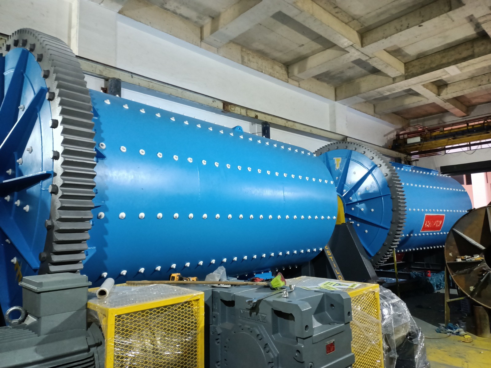
Grinding · Process equipment engineering
Horizontal rod mill systems sized from material and circuit data for duties requiring controlled product distribution and limited overgrinding.
Technical data
| Model | Drum diameter (mm) | Mill length (mm) | Motor power (kW) | Mill speed (rpm) | Steel rod filling ratio (%) | Steel rod charge (t) | Liner type | Drive system | Approx. weight (t) |
|---|---|---|---|---|---|---|---|---|---|
| EST-RM-1800 | 1.800 | 3.000–6.000 | 75–160 | 16–24 | 30–40 | 6–15 | Çelik / Kauçuk / Alümina / Döküm | Redüktör + Dişli-Pinyon | 30–70 |
| EST-RM-2200 | 2.200 | 3.500–7.000 | 110–250 | 14–20 | 30–40 | 12–30 | Çelik / Kauçuk / Alümina / Döküm | Redüktör + Dişli-Pinyon | 50–120 |
| EST-RM-2600 | 2.600 | 4.000–8.000 | 160–400 | 13–18 | 30–40 | 20–50 | Çelik / Kauçuk / Alümina / Döküm | Redüktör + Dişli-Pinyon | 90–200 |
| EST-RM-3000 | 3.000 | 4.500–9.000 | 250–630 | 12–15 | 30–40 | 30–80 | Çelik / Kauçuk / Alümina / Döküm | Redüktör + Dişli-Pinyon | 130–300 |
| EST-RM-3400 | 3.400 | 5.000–10.500 | 315–900 | 11–15 | 30–40 | 45–120 | Çelik / Kauçuk / Alümina / Döküm | Redüktör + Dişli-Pinyon | 190–420 |
| EST-RM-3800 | 3.800 | 5.500–10.500 | 400–1.200 | 10–14 | 30–40 | 60–170 | Çelik / Kauçuk / Alümina / Döküm | Redüktör + Dişli-Pinyon | 260–560 |
| EST-RM-4200 | 4.200 | 6.000–11.500 | 560–1.600 | 9–13 | 30–40 | 85–240 | Çelik / Kauçuk / Alümina / Döküm | Redüktör + Dişli-Pinyon | 380–760 |
| EST-RM-4600 | 4.600 | 6.500–11.500 | 800–2.200 | 8–12 | 30–40 | 120–330 | Çelik / Kauçuk / Alümina / Döküm | Redüktör + Dişli-Pinyon | 520–980 |
| EST-RM-5000 | 5.000 | 7.000–12.500 | 1.000–3.800 | 8–11 | 30–40 | 160–450 | Çelik / Kauçuk / Alümina / Döküm | Redüktör + Dişli-Pinyon | 680–1.300 |
| EST-RM-5600 | 5.600 | 7.500–13.600 | 1.600–3.600 | 7–10 | 30–40 | 220–620 | Çelik / Kauçuk / Alümina / Döküm | Redüktör + Dişli-Pinyon | 1.100–2.800 |
| EST-RM-6000 | 6.000 | 8.000–13.000 | 2.000–4.500 | 7–9 | 30–40 | 280–800 | Çelik / Kauçuk / Alümina / Döküm | Redüktör + Dişli-Pinyon | 1.600–2.800 |
Rod mills are evaluated where linear grinding contact and a more controlled particle distribution are important to the process duty.
Rods inside the rotating shell create linear contact across the material bed. Feed distribution, rod charge, speed and discharge arrangement are evaluated together.
A controlled intermediate grinding stage between crushing and finer grinding or classification; its actual circuit position is determined from material tests and the product target.
Process integration
Feeding, grinding, classification, recirculation and product collection are evaluated as one connected process.
Quotation basis
A reliable quotation requires material, duty and site inputs; a fixed price is not published without an engineering review.
Interactive product anatomy
Rotate the machine through 360° and inspect the shell, liners, grinding charge, bearings and drive train in transparent, section or exploded view.
Engineering basis
Final capacity, motor power and dimensions are confirmed only after material and site inputs are evaluated.
Production and field
Engineering insights
Technical request