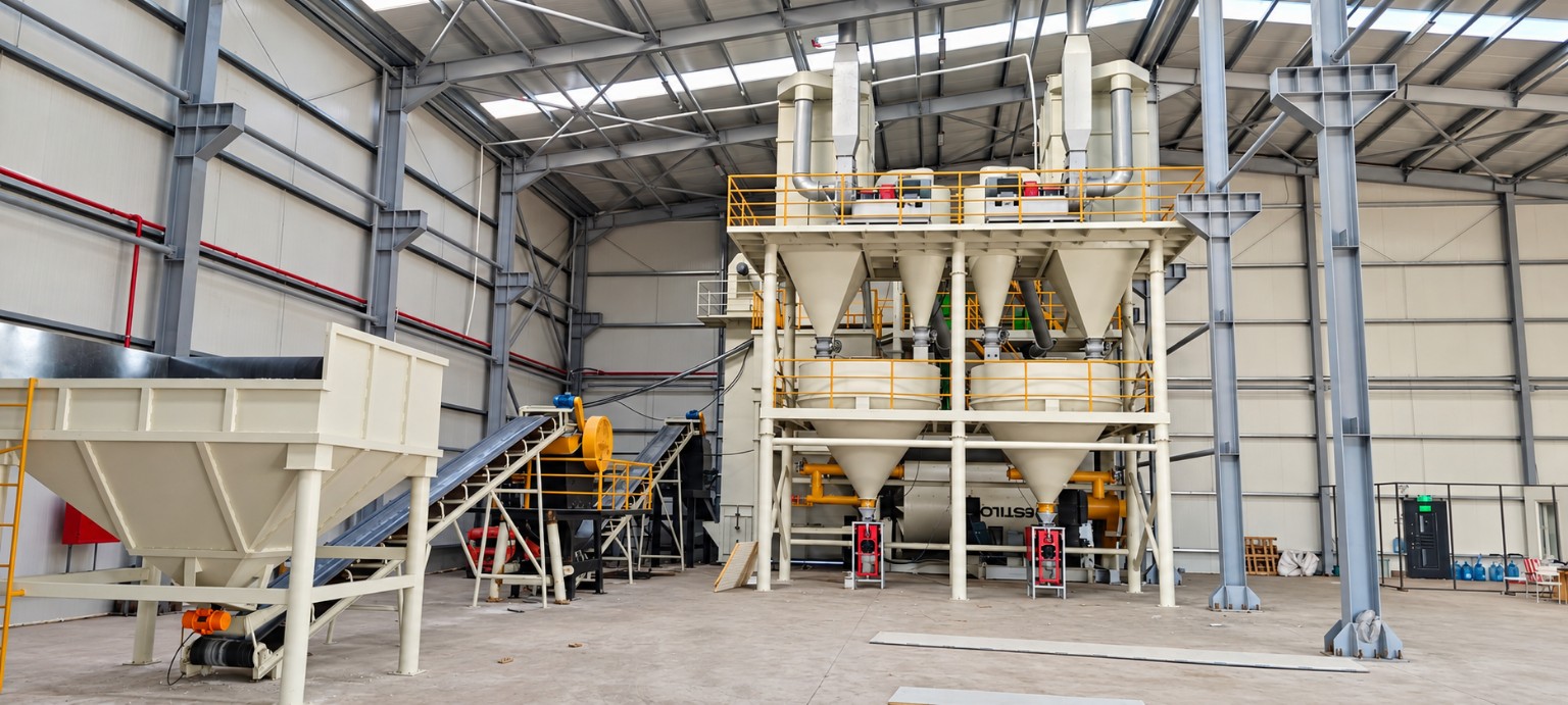
Intended use
Applied in dry grinding circuits where fines and coarse return material must be separated.
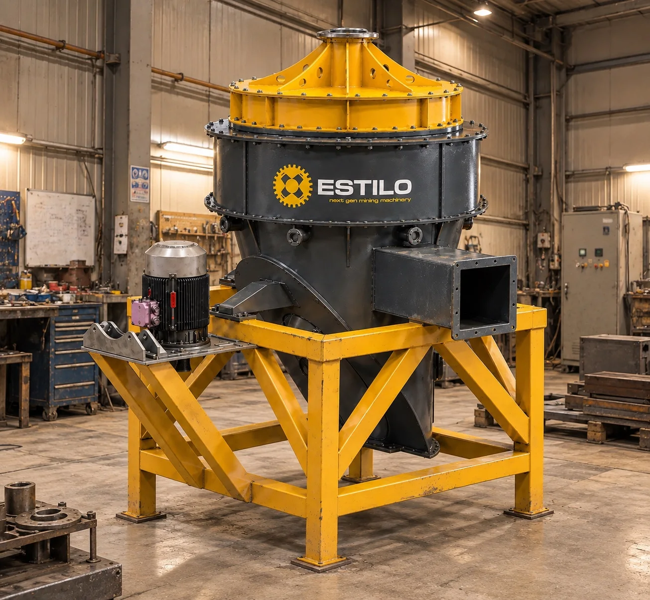
Classification · Process equipment engineering
Air classification systems separating ground material by particle size through controlled airflow and rotor action.
Technical data
| Model | Feed capacity (t/h) | Fan diameter (mm) | Motor power (kW) | Air flow (m³/h) | d97: 20 µm (t/h) | d97: 45 µm (t/h) | d97: 63 µm (t/h) | d97: 90 µm (t/h) |
|---|---|---|---|---|---|---|---|---|
| EST-SEP-500 | 1,5–8 | 500 | 15 | 7.000 | 1,5 | 2,7 | 3,4 | 4,4 |
| EST-SEP-650 | 2,5–15 | 650 | 22 | 12.000 | 2,5 | 4,3 | 5,5 | 7 |
| EST-SEP-800 | 5–25 | 800 | 30 | 20.000 | 4 | 7 | 8,8 | 11 |
| EST-SEP-1000 | 8–40 | 1.000 | 55 | 36.000 | 6 | 10 | 14 | 18 |
| EST-SEP-1300 | 10–60 | 1.300 | 75 | 50.000 | 10 | 16 | 22 | 28 |
| EST-SEP-1600 | 20–80 | 1.600 | 110 | 65.000 | 14 | 24 | 30 | 39 |
Applied in dry grinding circuits where fines and coarse return material must be separated.
Air drag and centrifugal force at the rotor determine particle separation.
The classification point controlling product fineness and circulating load.
Process integration
Feed distribution, air handling, cut duty, coarse return and product collection are evaluated as one connected process.
Quotation basis
A reliable quotation requires material, duty and site inputs; a fixed price is not published without an engineering review.
Interactive product anatomy
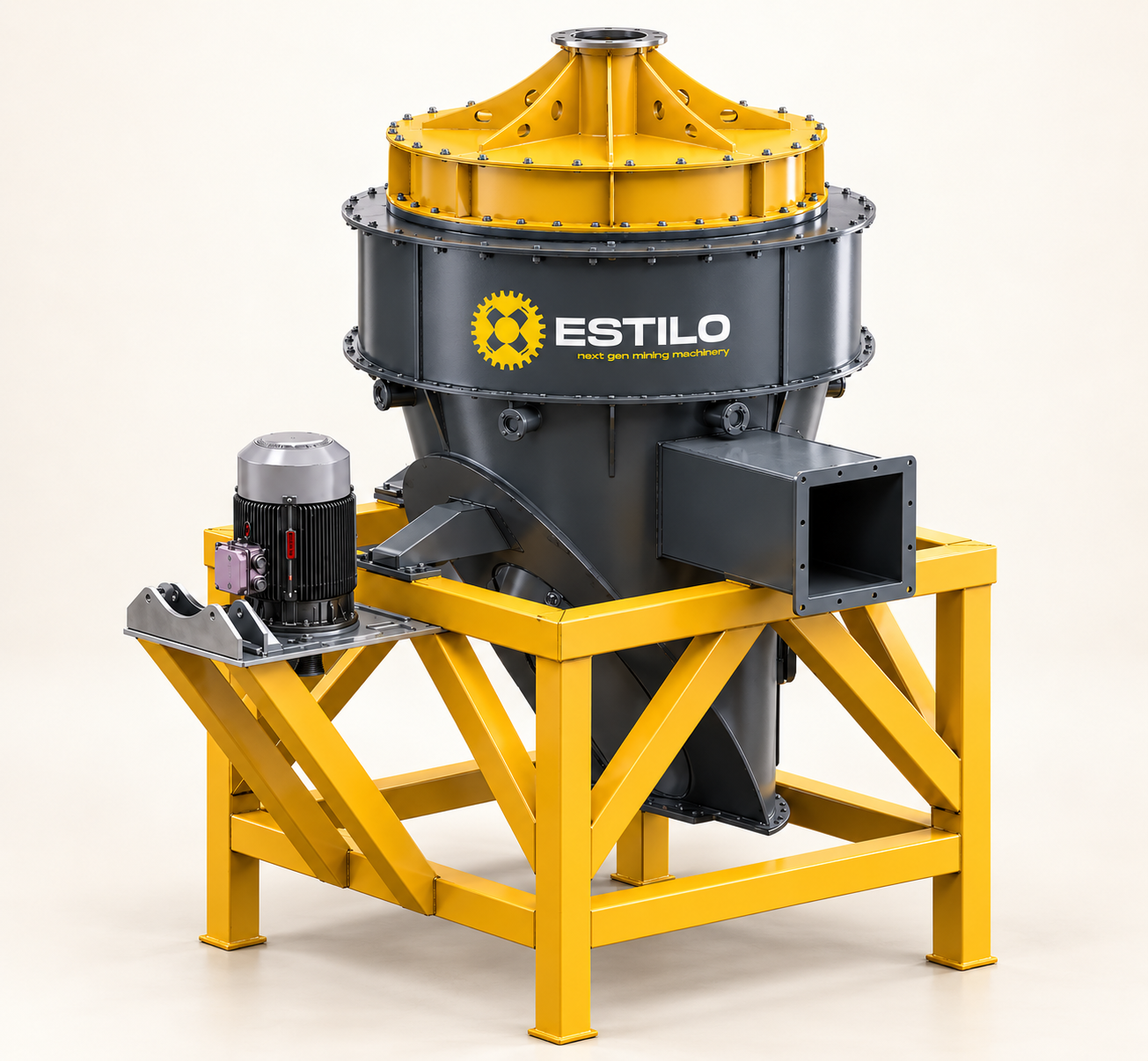
Rotate the model freely and inspect the rotor, blades, main shaft, drive and air-material connections up close.
 FULL-SCALE AR
AUGMENTED REALITY
Use your phone or tablet camera to place the CAD-derived separator on the factory floor and review its footprint before an engineering visit.
CAD envelope: 2,997 × 2,450 × 4,022 mm (width × depth × height)
Scan the QR code with your camera, then tap the AR button on the page.
For the most stable placement, scan the floor for a few seconds before positioning the model and move around it slowly. AR is for spatial review; approved drawings remain authoritative.
Engineering basis
Final capacity, motor power and dimensions are confirmed only after material and site inputs are evaluated.
Production and field
Field reference
Engineering insights
Technical request