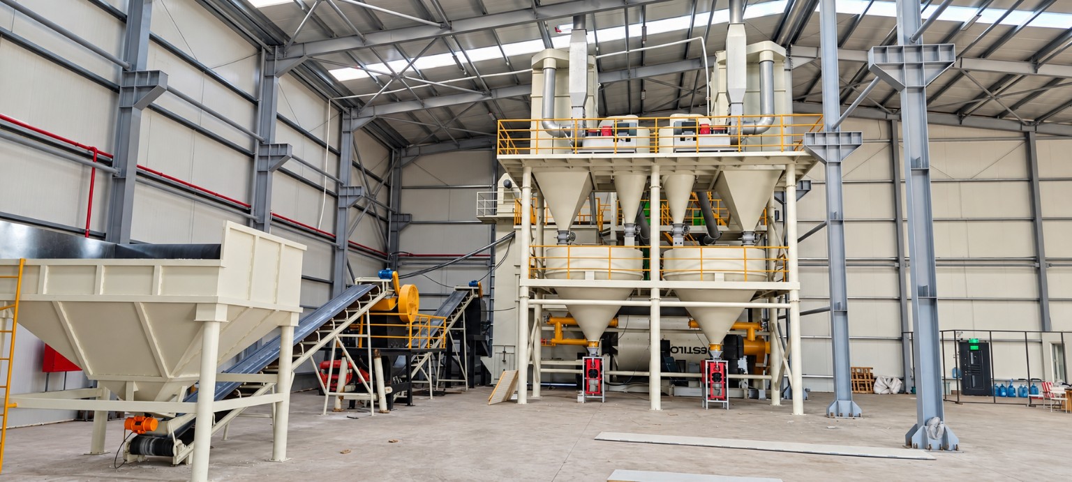
Intended use
Ball mills are evaluated for dry or wet circuits requiring a finer product, either as a stand-alone duty or in closed circuit with classification equipment.
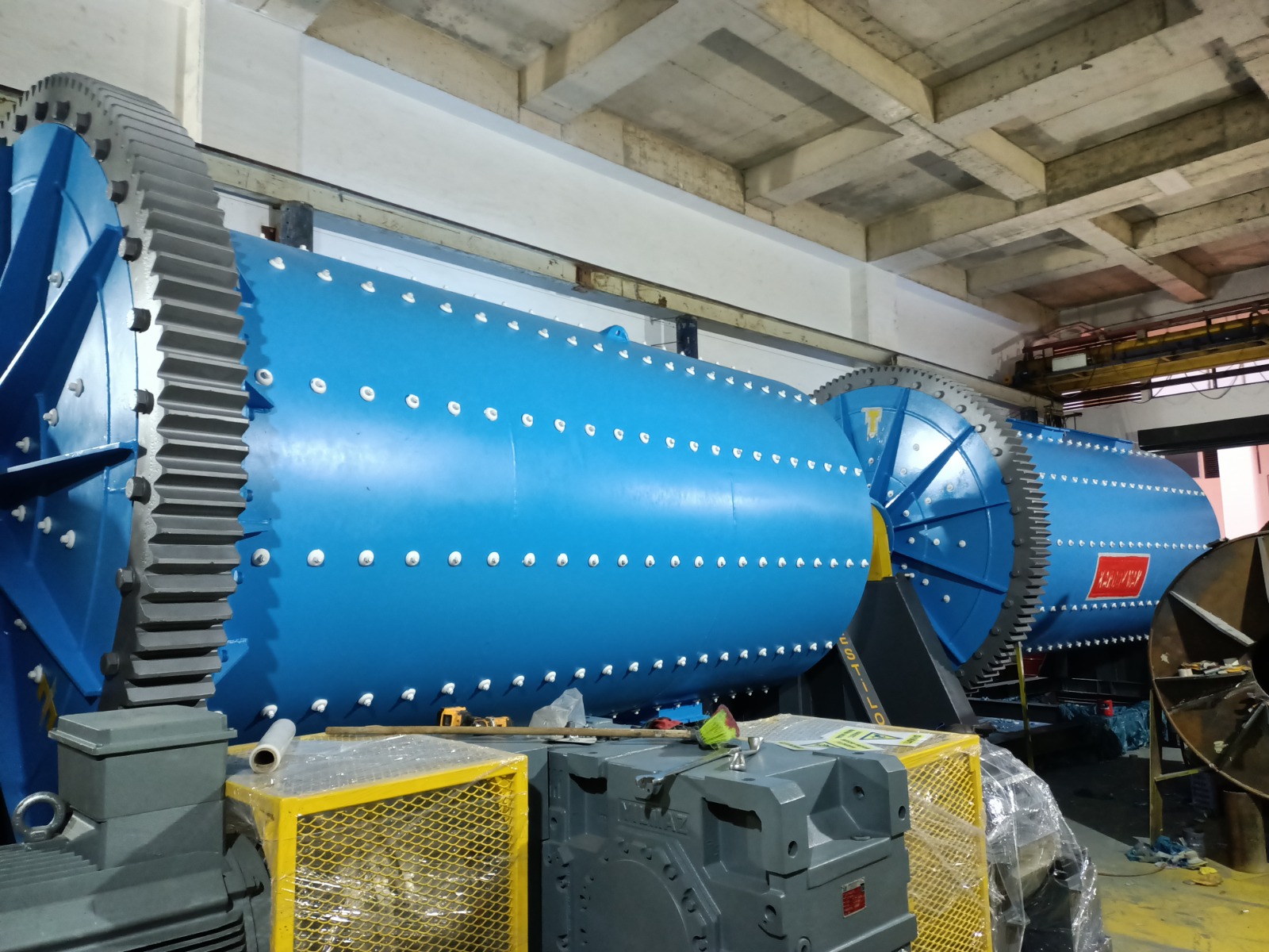
Grinding · Process equipment engineering
Horizontal ball mill systems sized for dry or wet industrial fine-grinding duties in mineral and ore-processing circuits according to target product fineness and feed characteristics.
Technical data
| Model | Drum diameter (mm) | Mill length (mm) | Motor power (kW) | Mill speed (rpm) | Steel ball filling ratio (%) | Steel ball charge (t) | Liner type | Drive system | Approx. weight (t) |
|---|---|---|---|---|---|---|---|---|---|
| EST-BM-1800 | 1.800 | 2.000–6.000 | 75–200 | 16–24 | 30–45 | 6–20 | Çelik / Kauçuk / Alümina / Döküm | Redüktör + Dişli-Pinyon | 30–70 |
| EST-BM-2200 | 2.200 | 2.500–7.000 | 132–400 | 14–20 | 30–45 | 13–40 | Çelik / Kauçuk / Alümina / Döküm | Redüktör + Dişli-Pinyon | 50–120 |
| EST-BM-2600 | 2.600 | 3.000–8.000 | 200–630 | 13–18 | 30–45 | 20–65 | Çelik / Kauçuk / Alümina / Döküm | Redüktör + Dişli-Pinyon | 90–200 |
| EST-BM-3000 | 3.000 | 3.500–8.500 | 400–1.100 | 12–16 | 30–45 | 32–95 | Çelik / Kauçuk / Alümina / Döküm | Redüktör + Dişli-Pinyon | 130–300 |
| EST-BM-3400 | 3.400 | 4.000–9.000 | 560–1.600 | 11–15 | 30–45 | 48–140 | Çelik / Kauçuk / Alümina / Döküm | Redüktör + Dişli-Pinyon | 190–420 |
| EST-BM-3800 | 3.800 | 4.500–9.500 | 800–2.200 | 10–14 | 30–45 | 64–180 | Çelik / Kauçuk / Alümina / Döküm | Redüktör + Dişli-Pinyon | 260–560 |
| EST-BM-4200 | 4.200 | 5.000–10.000 | 1.000–2.800 | 9–13 | 30–45 | 90–240 | Çelik / Kauçuk / Alümina / Döküm | Redüktör + Dişli-Pinyon | 380–760 |
| EST-BM-4600 | 4.600 | 5.500–10.500 | 1.500–3.600 | 8–12 | 30–45 | 115–320 | Çelik / Kauçuk / Alümina / Döküm | Redüktör + Dişli-Pinyon | 520–980 |
| EST-BM-5000 | 5.000 | 6.000–11.000 | 2.000–4.500 | 8–11 | 30–45 | 150–420 | Çelik / Kauçuk / Alümina / Döküm | Redüktör + Dişli-Pinyon | 680–1.300 |
| EST-BM-5600 | 5.600 | 6.500–11.500 | 3.000–4.500 | 7–10 | 30–45 | 210–620 | Çelik / Kauçuk / Alümina / Döküm | Redüktör + Dişli-Pinyon | 1.100–2.000 |
| EST-BM-6000 | 6.000 | 7.000–12.000 | 4.000–6.000 | 7–9 | 30–45 | 265–900 | Çelik / Kauçuk / Alümina / Döküm | Redüktör + Dişli-Pinyon | 1.600–2.800 |
Ball mills are evaluated for dry or wet circuits requiring a finer product, either as a stand-alone duty or in closed circuit with classification equipment.
A ball charge inside the rotating shell reduces material by impact and abrasion. Speed, filling, liner geometry and residence time are evaluated together with process data.
The main grinding stage creating the target fineness after crushing or primary grinding, integrated where required with separation, hydrocycloning, conveying and product collection.
Process integration
Feeding, grinding, classification, recirculation and product collection are evaluated as one connected process.
Quotation basis
A reliable quotation requires material, duty and site inputs; a fixed price is not published without an engineering review.
Interactive product anatomy
Rotate the real 3D machine model through 360° and inspect the shell, bearings and drive arrangement.
 FULL-SCALE AR
AUGMENTED REALITY
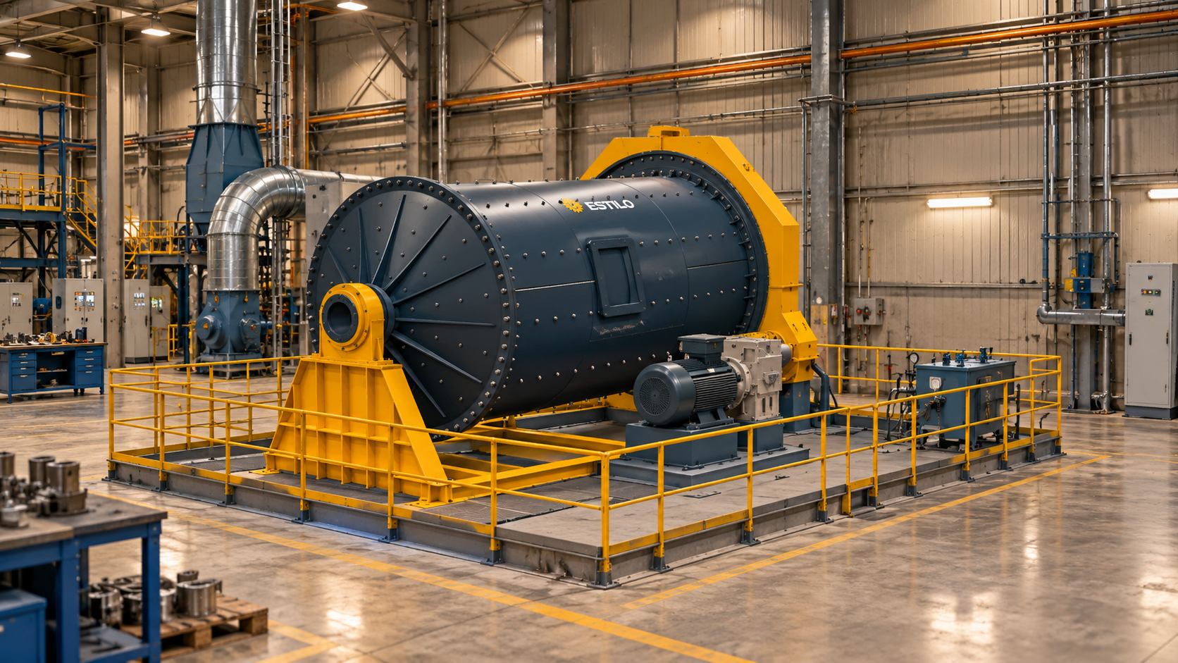
Use your phone or tablet camera to place the CAD-derived ball mill on the factory floor at full scale and review the layout including the mill body, drive assembly, frame and steel platform.
CAD envelope: 10,000 × 8,000 × 4,511 mm (length × width × height)
Scan the QR code with your camera, then tap the AR button on the page.
For the most stable placement, scan the floor for a few seconds before positioning the model and move around it slowly. AR is for spatial review; approved drawings remain authoritative.
Engineering basis
Final capacity, motor power and dimensions are confirmed only after material and site inputs are evaluated.
Production and field
Field reference
Engineering insights
Technical request