
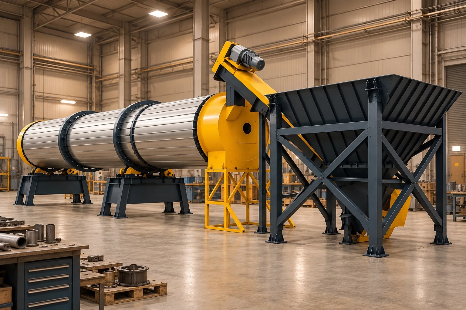
A rotary dryer removes moisture by moving solids through a rotating drum and transferring heat through direct gas contact or an indirectly heated surface. Sizing requires the dry-solids balance, water evaporation rate, material drying behaviour, heat transfer, gas system and target outlet conditions to be verified together.
What is a rotary dryer?
A rotary dryer reduces moisture while conveying feed through a rotating cylindrical shell and enabling heat and mass transfer. The duty is not simply to heat material; it is to reach the target moisture without compromising product quality or plant safety.
Physical basis of drying
Heat transferred to wet solids converts surface and internal water into vapour, which must then move into the surrounding gas phase. Drying rate therefore depends on internal moisture movement, gas humidity capacity, contact area and time as well as temperature.
How does material move inside the drum?
Drum rotation, slope and internals convey the solids axially. Flights can pick up material and shower it through the gas stream, increasing gas–solid contact area.
Flight design
Flight geometry, loading and bulk-material behaviour affect discharge angle, gas contact and residence-time distribution. Peer-reviewed studies show that these variables interact; there is no universal flight geometry for every material.
Why is capacity more than tonnes per hour?
Two feeds with the same wet throughput can require very different water removal when inlet and target outlet moisture differ. The dry-solids balance must therefore be closed before evaporation duty, heat demand and gas handling are evaluated together.
Start with the mass balance
Every moisture value must state whether it is wet basis or dry basis. Mixing the two bases directly changes the calculated product rate and water removal.
Direct and indirect drying
| Arrangement | Heat transfer | Selection topics |
|---|---|---|
| Direct | Hot gas contacts the material | Product–gas compatibility, emissions, dust, heat and mass transfer |
| Indirect | Heat crosses a surface into the material | Product isolation, wall temperature, fouling, area and cleaning |
Separate thin pages were not created for these two arrangements; their selection logic remains in this principal guide to avoid topic overlap.
Co-current and counter-current flow
In co-current flow, hot gas and solids travel in the same direction; in counter-current flow they travel in opposite directions. Flow direction is selected from thermal sensitivity, target product temperature, drying curve, gas conditions and energy balance.
Neither direction is universally superior
Peer-reviewed comparisons show that performance depends on the application and boundary conditions. Results from another material cannot be copied directly into a new design.
How is residence time evaluated?
Mean residence time alone is insufficient: distribution width, short-circuiting solids and overly retained fractions can also affect product moisture. Drum geometry, slope, speed, flights, fill, solids rate and gas velocity interact.
Connect models with tests
Representative material tests, tracer measurements or a validated process model can connect theoretical residence time with plant behaviour. This guide publishes no fixed number of minutes.
Heat duty and real-system losses
A preliminary sensible-heat term can be written Q_sens = m × Cp × ΔT, while phase change can be written Q_evap = m_evap × h_fg. The real duty also includes heating solids and retained water, evaporation, process-gas heating, shell/leakage/stack losses and operating regime.
Cp and h_fg vary with temperature and conditions. These expressions alone do not set burner rating, fuel use or dryer dimensions.
Engineering data required for selection
| Input | Data to verify | Design impact |
|---|---|---|
| Feed | Normal/design rate and variability | Dry solids and evaporation duty |
| Moisture | Inlet/outlet target and stated basis | Water balance and product condition |
| Material | PSD, density, stickiness and abrasiveness | Transport, flights and contact |
| Thermal behaviour | Heat capacity, sensitivity and drying kinetics | Temperature limit and residence time |
| Gas system | Source, flow, humidity, temperature and pressure loss | Heat/mass transfer and fan duty |
| Emissions | Dust, vapour and possible constituents | Filter, ducting and safety scope |
| Site | Layout, maintenance and utilities | Mechanical and process integration |
Dust, gas and product collection
Dryer exhaust can carry fine solids together with water vapour. Ducting, cyclone/filter, fan, seals and product collection are designed within one pressure and mass balance.
The downstream process
When dry product feeds grinding or air classification, residual moisture, temperature and agglomeration affect the next equipment's feed behaviour. The dryer is part of the connected process target, not an isolated island.
Sizing and quotation checklist
- State wet- or dry-basis moisture consistently
- Separate normal, design and transient feed rates
- Verify drying and stickiness with representative samples
- Close dry-solids and evaporation balances
- Define product-temperature and thermal-damage limits
- Select direct/indirect arrangement and flow direction from process evidence
- Verify residence time and internals against material movement
- Calculate heat source, fan, filter and ducting as one system
- Include access, emissions and site safety in layout
Without verified project data, no fixed capacity, drum dimension, temperature, speed, motor power, airflow, residence time or efficiency is published.
