
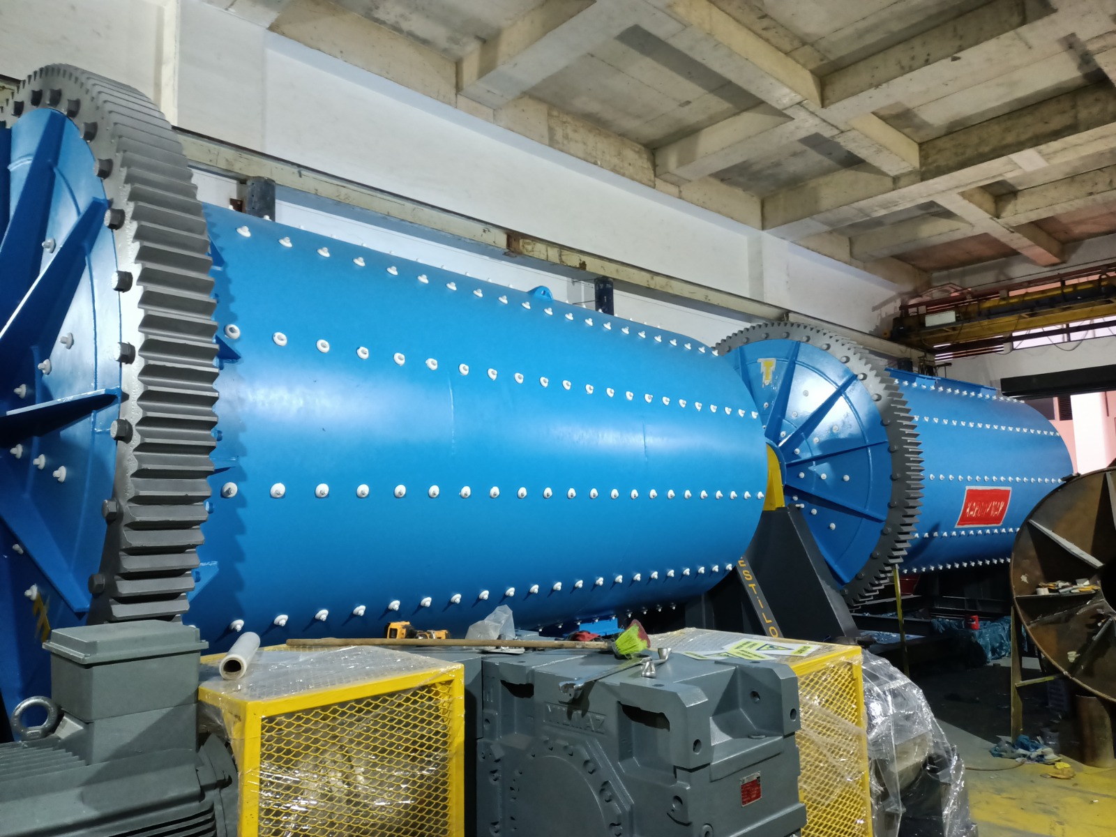
Ball-mill maintenance is based on recorded inspection of liners and fasteners, drive and bearings, lubrication, seals, vibration and temperature trends. Intervention intervals depend on the equipment, duty and manufacturer instructions.
The basis of safe maintenance
Before inspection or intervention, energy sources must be safely isolated, the rotating mass secured and site procedures followed. This article does not replace the manufacturer manual or an authorized risk assessment.
Records and trends
Rather than one isolated measurement, comparable vibration, temperature, lubricant and wear readings from consistent points are trended over time.
Liners and fasteners
Liners protect the shell from wear and influence charge motion. Uneven wear, loosening, cracking, deformation or leakage around fasteners should be evaluated against manufacturer criteria.
Liner management
- Record wear distribution by location
- Compare change with product and operating data
- Inspect fasteners and sealing together
- Base replacement on remaining section, manufacturer limit and risk review
Why no service-life figure is published
Liner life depends on abrasiveness, media charge, liner material/profile and operating conditions. No hour or tonnage value is stated without verified equipment data.
Drive, gear-pinion and bearings
Gear contact pattern, surface condition, abnormal noise, lubrication and guard condition are checked under the applicable manufacturer procedure. Bearing temperature and vibration trends, lubricant leakage and alignment/fastener signs are evaluated together.
Alignment and balance indications
One-sided wear, repeatable vibration components or changes at couplings and foundations can require alignment and balance investigation. Replacing a component without confirming root cause is not a complete corrective action.
Lubrication, temperature and leakage
Oil level, pressure/flow indications, filter condition and visual or analytical lubricant findings are monitored against the system instructions. A temperature increase must be interpreted with load, ambient condition, lubrication and measurement location.
Lubricant type, change interval, alarm temperature and tolerance must come from verified manufacturer documentation; no general number is given here.
Maintenance check matrix
| Area | General indication | Verification approach |
|---|---|---|
| Liners | Uneven wear, crack, loosening | Measurement record and manufacturer limit |
| Fasteners | Loosening, deformation, leakage | Approved tightening and inspection procedure |
| Gear-pinion | Contact pattern, surface, noise, lubrication | Manufacturer contact/lubrication criteria |
| Bearings | Vibration, temperature, lubricant condition | Trend and root-cause analysis |
| Sealing | Dust, product or lubricant leakage | Locate source and confirm suitable part |
| Foundation/coupling | Movement, alignment or fastener indication | Measurement and alignment check |
How is a maintenance plan built?
- Start with equipment and component manufacturer manuals
- Give each critical inspection point a unique identity
- Separate running and shutdown inspections by risk
- Standardize the measurement method and reference condition
- Relate changes to process data
- Record ownership, action and closure for each finding
This approach does not specify fixed intervals, liner or bearing life, oil-change hours or acceptance tolerances; those values require verified equipment- and site-specific documentation.