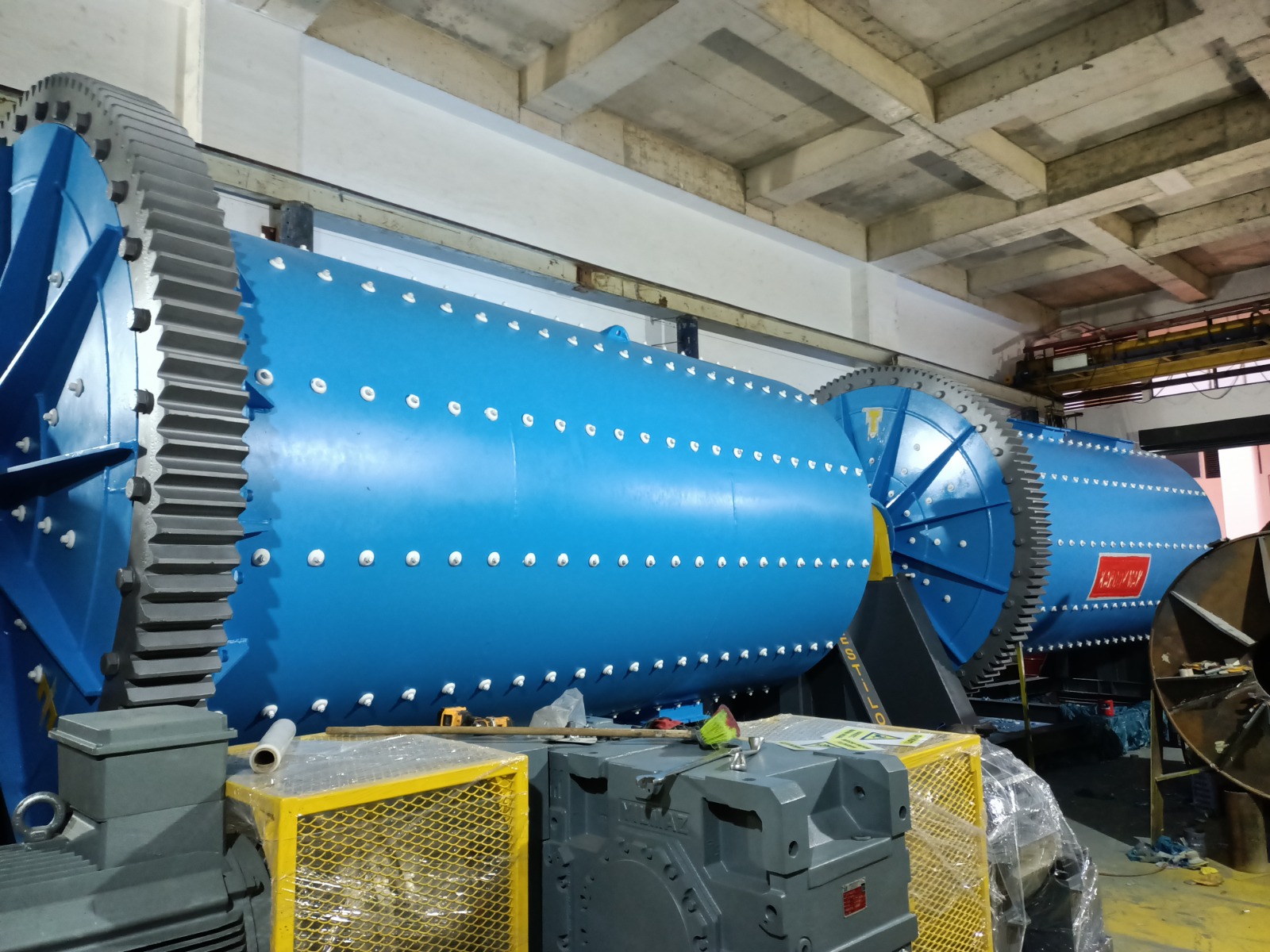
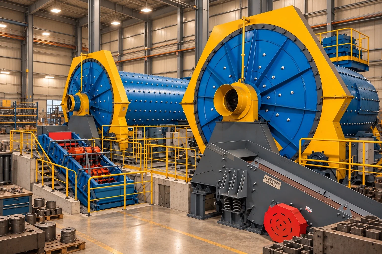
A rod mill is a grinding machine that reduces particle size through the impact, rolling and line contact generated by long steel rods inside a rotating cylindrical shell.
What is a rod mill?
A rod mill uses long steel rods aligned along the shell axis as its grinding medium. For a suitable duty, it can reduce coarse or intermediate feed into a more controlled distribution or prepare material for a downstream grinding stage.
The equipment name alone does not define its duty. Feed distribution, breakage behaviour, target product and downstream processing must be established before any capacity or product-size claim can be made.
Working principle and line contact
As the shell rotates, rods and material are lifted before rolling, sliding and falling motion transfers mechanical energy. Linear contact zones between the long rods can help capture coarse particles selectively when the feed and duty are suitable.
Why does rod arrangement matter?
Rod length, diameter distribution, filling, shell geometry and operating conditions influence parallel motion and contact with the feed. These variables require process definition and supplier engineering rather than catalogue selection alone.
Generation of excessive fines
Rod grinding can help limit excessive fines in a suitable duty, but the outcome is material-specific and cannot be stated as a numerical improvement without representative testwork.
Difference from a ball mill
A ball mill creates a larger population of point and multi-directional contacts, while a rod mill emphasises line contact between long rods. Rod mills are therefore commonly evaluated for controlled coarse or intermediate grinding, and ball mills for finer duties.
Circuit duty and application boundary
A rod mill may operate in an open circuit, as an intermediate stage feeding another mill, or in another flowsheet suited to the process. Crushing, screening, classification and downstream product requirements are evaluated across the complete line.
Rod–ball circuit
Placing a rod mill before a ball mill is one possible arrangement; it is not automatically required or optimal for every material.
Main components
- Rotating shell and internal liners
- Selected rod charge
- Feed and discharge arrangement
- Drive and coupling system
- Bearings and lubrication
- Guards, access and auxiliary systems
Inputs required for engineering selection
- Representative feed sample and size distribution
- Feed top size and target product distribution
- Material grindability and abrasion behaviour
- Wet or dry process basis
- Open/closed circuit and downstream duty
- Plant capacity target, schedule and availability
- Site layout, maintenance access and energy constraints
Final diameter, length, rod charge, motor power and capacity require verified test data and supplier engineering.